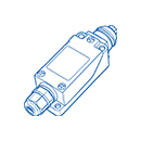

A micro switch should be selected as an electromechanical component, not only by its body size. The contact rating must suit the circuit, while the actuator and travel must match the machine movement. A mismatch in either area can shorten contact life or damage the mechanism.
Check voltage, current and whether the published value applies to a resistive load. Motors, solenoids, lamps and capacitive power supplies can produce inrush current or electrical arcing that differs from a resistive circuit. For low-level electronic signals, contact material and minimum applicable load may also matter.
Many snap-action micro switches provide COM, NO and NC terminals. Confirm which circuit state is required before and after actuation. For safety-related or monitored circuits, the complete control design must determine how the contacts are used; the presence of NO and NC terminals alone does not make a switch a safety device.
A pin plunger suits direct, accurately aligned movement. A hinge lever reduces the force needed at the point of contact and accommodates a wider target path. A roller lever is useful when a moving cam or part passes across the actuator. Simulated roller and extended-lever options can solve space constraints, but their force and travel characteristics differ.
Review pretravel, operating position, overtravel, movement differential and total travel. The machine should move the actuator far enough for reliable switching without exceeding the permitted travel. Allow for production tolerance, target wear, vibration and mounting variation rather than testing only one prototype.
Mechanical life and electrical life are different specifications. Electrical life depends on voltage, current, load type, switching frequency and environmental conditions. Ask for the model-specific test conditions when expected cycle life is important.
Solder, quick-connect, PCB and wire-lead versions support different assemblies. Confirm mounting-hole positions, screw size and datum surfaces. Dust, moisture, temperature and contamination may require a sealed model, but the final enclosure and cable entry must also be considered.
Provide voltage, current, load type, contact arrangement, actuator movement, available operating force, target direction, mounting dimensions, terminal type, switching frequency and environment. A drawing or photo of the mechanism helps verify the actuator geometry.
Compare available models in the XURUI micro switch range. Send the circuit and installation details through the quotation form for model-selection support.