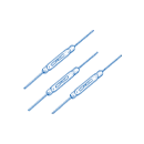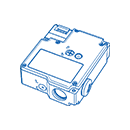

A reed switch and a Hall effect sensor can both respond to a magnetic field, but they produce different electrical outputs. Selection starts with the controller input, available power and the way the magnet moves relative to the sensing device.
A reed switch uses magnetic force to move sealed contacts. Depending on the contact form, it can provide a normally open or normally closed circuit. A Hall effect sensor is an electronic device that detects magnetic flux and needs a suitable power supply; its output may be digital or analog depending on the model. Do not assume the two devices can be wired interchangeably.
A simple reed contact can often be read as a switch input without powering the sensing element. A Hall sensor requires supply voltage and a compatible output circuit. Check input pull-up or pull-down arrangements, output polarity, current limits and electrical noise in the complete system.
Mechanical contacts can bounce during transition and have model-specific electrical life. An electronic Hall sensor has no moving contact, which can help in frequent sensing applications. Compare response time and switching frequency against the application; the controller may need filtering or debouncing for either solution.
Operating distance is not a fixed property of the sensor alone. Magnet strength, orientation, travel, mounting tolerance and nearby ferromagnetic material can change the field at the device. Test the full assembly over the expected temperature and mechanical tolerances. For a reed switch, also check its sensitivity, contact rating and glass package handling requirements.
Use a reed switch where a contact-style output fits the circuit and its rating and switching life are suitable. Consider a Hall sensor when an electronic output, higher sensing frequency or an analog field measurement is needed. Verify the chosen part in the installed design.
See the XURUI reed switch range and the reed sensitivity guide for further model-selection questions.