Product Introduction & Process
-
1
Safety-Critical Material Inspection
Housing materials, contact alloys, terminals, springs, locking components, operation keys, solenoids, seals, and cable glands are inspected. Safety-related components receive enhanced dimensional and material verification.
2
Housing Forming and Precision Machining
Metal housings are die-cast and machined, while plastic housings are precision injection molded. Key insertion slots, rotating-head interfaces, mounting holes, terminal chambers, and locking interfaces are produced within controlled tolerances.
3
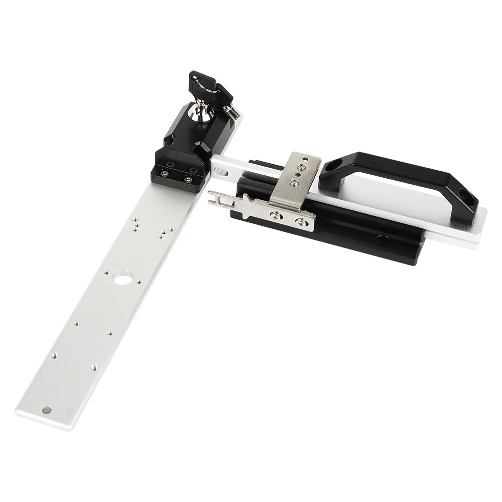
Operation Key Manufacturing
Operation keys are stamped, formed, machined, and surface-treated. Key thickness, insertion profile, mounting holes, strength, and engagement dimensions are inspected to ensure reliable interaction with the switch head.
4
Contact and Terminal Production
Copper-alloy terminals and contact carriers are precision stamped. Silver or gold-alloy contact points are riveted or welded onto the contact components according to the required load and signal level.
5
Direct-Opening Contact Mechanism Assembly
Normally closed safety contacts are assembled with a mechanically driven direct-opening structure. The mechanism is designed so that actuator movement physically separates the safety contacts rather than relying only on spring force.
6
Mechanical Interlock Assembly
Cams, plungers, shafts, guide components, return springs, key-detection parts, and locking elements are assembled. Component alignment and movement are controlled to prevent false operation or incomplete contact transfer.
7
Solenoid Locking Module Assembly
For guard-locking models, the electromagnetic coil, armature, locking pin, manual release mechanism, and monitoring contacts are assembled. Coil resistance, movement, locking engagement, and release performance are checked.
8
Rotating Head and Key Entry Assembly
The operating head is assembled and configured for the permitted key insertion directions. Key insertion, rotation, withdrawal, and head positioning are tested to ensure smooth operation without excessive clearance.
9
Terminal Wiring and Cable Entry Assembly
Terminal blocks, internal wires, connectors, protective earth components, and cable glands are installed. Wiring sequence and conductor fastening are checked to prevent incorrect safety-circuit connections.
10
Sealing and Housing Closure
Gaskets, O-rings, shaft seals, cable seals, and terminal covers are installed. Housing screws are tightened using controlled torque to maintain mechanical strength and the required environmental protection.
11
Safety Function Calibration
The key insertion position, contact opening position, locking point, release point, and monitoring-contact sequence are measured. The safety contacts must open within the specified actuator travel.
12
Locking and Mechanical Strength Testing
Guard-locking models are tested for locking force, key retention, manual release operation, repeated locking cycles, and resistance to mechanical pull or impact according to the applicable specification.
13
Electrical and Insulation Testing
Each unit is tested for contact continuity, forced-opening performance, contact resistance, insulation resistance, dielectric strength, coil operation, LED indication, and terminal accuracy.
14
Environmental and Endurance Verification
Sample units undergo mechanical life, electrical life, vibration, impact, temperature, humidity, dust, water, and cable pull testing according to product requirements.
15
Final Safety Inspection and Packaging
Safety markings, contact diagrams, key types, head direction, terminal covers, screws, sealing components, and accessories are checked. Products are batch-coded to maintain traceability of safety-critical components and inspections.